Hardware
Technology and electronics are constantly evolving and surprisingly fast. The measuring and control equipment that we purchased some time ago, we notice that in certain cases, it no longer manages to help us. And it was not cheap at all, we all know. Most of the time and that is how it happens, we purchase measuring and control equipment at the technical level of the moment, which in real life, with the passage of time, unfortunately, always and always lags behind. It is even worse when, due to limitations or lack of information, we purchase measuring equipment that does not cover a wide spectrum of the cases encountered in current activity. How do we choose our measuring and control equipment?
In this section, also born out of necessity, we propose an assessment of the current state-of-the-art technology, which we hope will be useful in choosing the measurement and control equipment for your own laboratory. The equipment presented here is not for advertising or their beauty, they were intentionally chosen for their analysis and precision performance, at the level of most complex chips manufactured today. The equipment presented is part of the DomoTicSys®tem Technologies portfolio and is used for commissioning, defectoscopy, calibration, design and research.
Let's see what these devices have in addition, at the same costs and what features to look for, the neglect of which could bring us many shortcomings and problems in the future. We hope it will be useful in your choices.
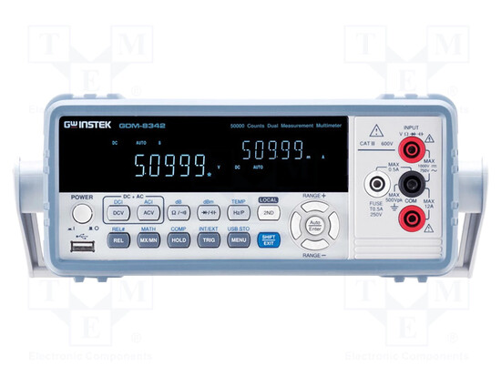
Benchtop multimeters, compared to portable ones, are generally recommended for the laboratory, for the precision and stability of measurements. For this reason, they are bulkier because they have incorporated specialized circuits for controlling and maintaining stability, to ensure accuracy. The present one has everything we would want from a multimeter, in terms of functions. The multitude of functions is a feature that we cannot afford to neglect. The manipulation interface offers access to all information even if it is a bit intimidating; it is a feature of current interfaces. We benefit from maximum precision and stability. From collateral investigations - we still need and it is good to inquire from various sources about the device we intend to purchase - we found out in this case that large companies in the field use it for its qualities, for calibration - and this is no small thing for a manufacturer. Measuring and control equipment is not purchased for its beauty and interface, but for its characteristics and analysis capacity.
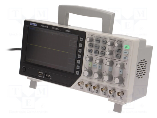
The desk oscilloscope is the mainstay and indispensable piece of equipment for measuring and control. Because we can clearly see on the display what is "there"! Of course, there are the waveforms, their size and characteristics, the sequence of digital signals without which we would otherwise "stumble" into them. But there is something else, that something that should make us think when purchasing an oscilloscope, because the costs are significant and if we make such a mistake, the costs will be double and the regrets painful. Here is what it is about. The modern chips that are used today and for many years to come, are designed in such a way as to reduce the costs of materials. That is, on an electronic assembly, instead of seeing 15 - 20 chips for example, we will see only 3 chips that will perform the same functions, even much more. This was achieved, among other things, through serial communication between chips. How can this serial communication be visualized, dismantled and controlled? In this situation, it would seem that we are completely helpless and without help, the specter of a "black-box" looms frighteningly on the horizon, for our profession. Well, things are not like that because oscilloscope manufacturers have kept up with such technologies and have managed to make oscilloscopes capable of analyzing the waveforms that participate in serial communication between chips. The conclusion is that when purchasing an oscilloscope, these things must be weighed carefully, that is, what activity and what investigation process will that oscilloscope participate in, in order to justify its future characteristics upon purchase. The one presented here, at almost the same cost, has the capacity to analyze serial communications between chips. These functions are indispensable for those who work in the digital field, with microcontrollers, because serial communication is actually done in software, in assembly language, meaning that the one who programs the microcontroller has total control over the sequence of waveforms in serial communication; he conceives it, he "crochets" it. It should be noted that the global trend in the electronics industry, and I've been doing this for a long time, is towards microprogrammed systems.
A careful analysis when purchasing an oscilloscope also has a very big advantage in completing the laboratory or workshop. If a digital multimeter has a built-in "small" frequency meter, which can be expanded by the way, a well-chosen digital oscilloscope always has a built-in frequency meter as a rule. And not only that. It is also equipped with a built-in signal generator that can also be modulated in MA and MF.
So with the same money or a small difference compared to other oscilloscopes, we can purchase three indispensable laboratory instruments in one, and all of very good quality and performance.
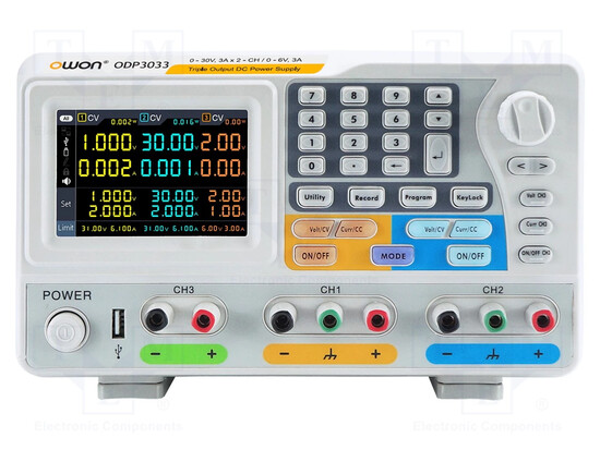
The indispensable voltage source in the laboratory is characterized by necessities. It is not absolutely necessary, the programmable, digital voltage source. The one presented here is recommended for those who do production (easily cover the costs), design, analysis, optimization and research in order to use new chips on the world market, unused in their own design, for introduction into manufacturing. What is interesting about such sources is that they have the ability to analyze, they have this facility introduced by the manufacturer, with which you can study and analyze the "health" of an electronic assembly. All projects start with a manufactured electronic assembly.
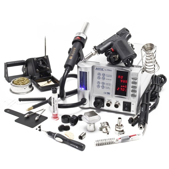
Under cost pressure, electronic components are also evolving towards SMDs, i.e. components without pins that are soldered directly to the board. All of us working in the field had to use chips with such a small package and pins so close together, almost impossible to solder even with the thinnest and best solder. This is the hot air soldering station. It was invented exactly for this purpose. In the desire of chip manufacturers, but also technological progress, to reduce material costs and miniaturize electronic products, passive and active SMD components (without pins) have already become established alongside chips with SSOP type packages, as just one example, more and more. Everything that is designed today is in SMD technology. Certain chips, otherwise common, are already manufactured only in SSOP capsules. The acquisition of a hot air station still raises problems, namely that the soldering area should be as narrow as possible, almost punctual, so as not to influence the other components. Then, the need for finer adjustment and control over the soldering is felt. What do all these actually mean. If you want to have as much control over the soldering as possible, you must also have a soldering station to measure. To have as many accessories as possible, to have control over the temperature, to have control over the circuit and air temperature, in a word, a station as complete as possible.
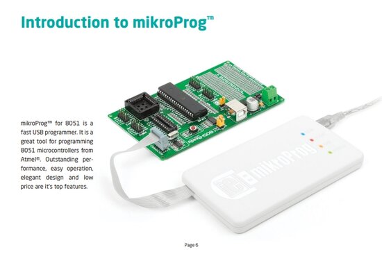
A special and indispensable accessory for those who work with microcontrollers is the programmer with which the chip is physically programmed. There are several families of microcontrollers, we will not go into details, it is an extremely complex field that requires years of study of digital electronics, assembly language programming and actual work with these chips. The one presented here, the programmer is for the Intel family, namely 80C51. It is suitable for large, tree-like systems with a large port capacity.
This microcontroller programming technology is accessible starting only from the electronics technician level.
This programmer together with its expansion board has been manufactured by https://www.mikroe.com/ for many years and is designed to work with the top range of the 8051 family. So it will be valid in the future for many years. However, with the transition from Win32 to Win64, respectively Windows 10 and especially Windows 11 (23H2), problems have arisen with the installation of drivers that Microsoft no longer wants to recognize because they are not signed. Microsoft also does not encourage the use of unsigned drivers, rightly so, and does not provide information on how to get out of such a situation. We reached the impasse of no longer being able to use the programmer on the newest Windows platforms. And it is a shame and regrettable because it is a very good and future-oriented programmer.
I considered it an onerous act, to help colleagues around the world, to provide in the following lines the procedure for installing these unsigned drivers, with the intention of extending the "life" of microProg 8051 on the newest Windows platforms.
Follow the following steps in order to accept, take control and install these drivers:
1. Start - Settings - System - Recovery - Advanced startup - Restart now - Choose an option - Troubleshoot - Advanced options - UEFI Firmware Settings - Restart - Startup Menu - F10 BIOS Setup (Utility) - go to Boot Options - go to Secure Boot - (with F5/F6) "Disabled" - Exit - Save Changes and Exit - Yes/Enter. (After you end your work session you will need to do this again but "Enable" Secure Boot as it was before!)
2. Start - (right click) Terminal (Admin); in Windows 10 is Command Prompt (Admin) - write next to the current line: "bcdedit /set testsigning on" - Enter/The operation completed successfuly - Restart (PC).
After you restart, at the bottom right you are notified of the "Test Mode" mode. In this mode you can install drivers that are not signed by Microsoft.
3. Try to understand the procedure as a whole. Install only drivers that you fully trust. In this mode, the PC is very vulnerable. Install the driver using the procedure described in the following lines (4.). Do your job with the application it serves, then be sure to switch to "bcdedit /set testsigning off" mode and reset the PC. The driver and its application will no longer work. The driver will be installed successfully, but it will only work in "Test Mode". If you have an application that needs to run all the time - usually industrial or dedicated - that PC should not work in a public network or connected to the internet, as it is very vulnerable to intrusion, in "Test Mode".
4. Driver preparatory installation: right click on the driver - Properties - Security - Advanced - to Owner:, click "Change" - Select User or Group - Enter the object name to select (examples):, write "Administrators" - Check Names - OK - check the check box "Replace owner on subcontainers and objects" - OK - Apply - OK - OK.
5. In this way, the driver is under the "care" of the administrator; its other prerogatives are taken away, which will be confirmed during installation: right-click on the driver - Run as administrator - Preparing setup - InstallShield Wizard Complete - Finish.
For our programmer we did exactly as shown above and it works very well. After we finish working with it, we exit "Test Mode" and validate Secure Boot "Enabled", and the PC is safe.
____________________________________________________________________________________________________________________________________________________
If you will have such kind measuring and control tools in your workshop, your work will definitely be a success.
It will follow.
Electronic components | Specialized magazines | Specialized books |